Hi levin818,
Sorry i wrongly given the product code. the correct Lumileds superflux led is
HPWT-RH02 RedOrange
Vf : 2.6V(typ)
If : 70mA(max)
Flux: (6.0-9.7lm)
I bought it while i was in Japan trip. LUMILEDS > SuperFlux - SuperFlux HPWT-RH02 RedOrange - LED
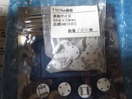
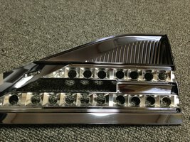
Why i don't want to go for series 4 or 3 LED because i'm not using any PCB board, I'm using T10Flux PCB for each superflux LED. (see image). I still can go for series 4 LED setup but max my tail lamp only got 17hole.(see image) 4LED x 4bank = 16Led balance 1LED how??
PS. To all sifu, sorry to mention i got no knowledge for electrical stuff. Hope all sifu can guide me hehe. Thanks
You have a good LED. Yes you can light up 17 LEDs in equal brightness but you need a constant current driver. Alternatively, you may use Voltage Regulator IC 7809 to clamp the voltage at 9v before supply it to the LED (as suggested by Shiro). It will have very close result with using constant current driver.
---------- Post added at 03:46 AM ---------- 6 hour anti-bump limit - Previous post was at 01:24 AM ----------
Since your LED didn't attach to any heat sink, it is advice not to drive it beyond 50mA (from the datasheet)
Lets fix tail light current at 30mA, brake light current at 50mA. You may reduce the current if you see that its too bright.
From your LED's V-I curve:
When I = 50mA, Vf = 2.45V
When I = 30mA, Vf = 2.26V
[Brake Light] (+) -- 7809 -- diode ---------┐
[Tail Light] ...(+) -- 7809 -- diode -- 6R2 --•-- 22R -- LED -- LED -- LED ---•-- (-)
............................................................└-- 22R -- LED -- LED -- LED --┘
............................................................└-- 22R -- LED -- LED -- LED --┘
............................................................└-- 22R -- LED -- LED -- LED --┘
............................................................└-- 22R -- LED -- LED -- LED --┘
[Brake Light] (+) -- 7809 -- diode ---------┐
[Tail Light] ...(+) -- 7809 -- diode -- 56R --•-- 75R ---------- LED -- LED ----- (-)
Diode = 1N4007, all resistor @ 1/4W 1% tolerance