- Joined
- Apr 18, 2006
- Messages
- 3,677
- Points
- 1,663
Well, all these adds up to experience.
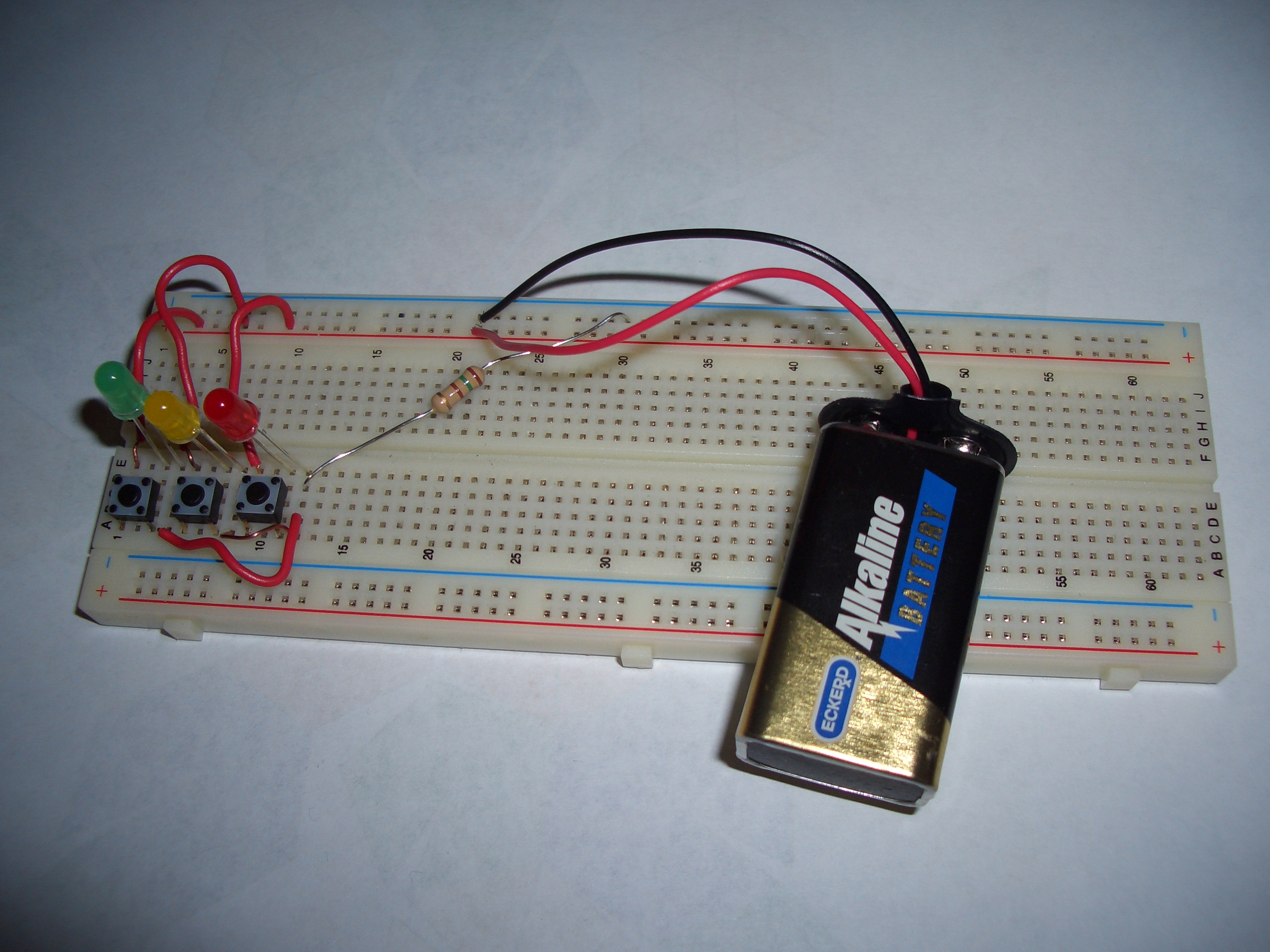
Btw, breadboard is plastic too right? Can it withstand the solder heat?
And plus, i just started to learn how to solder, i had a few cold solder. Bad.
you don't solder on breadboard.
a soldering aid like the soldering helper with arms are cheap rm20ish only and is a good buy if you solder often.
solder iron wattage also important. I use a 60-100w for car wires that are thick, and 25-40w for components.
Sent from my GT-I9100G using Tapatalk 2